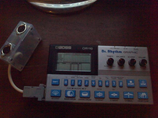
BOSS DR-110 MIDI SYNC
I find this unit cute and nice sounding, but it has the problem as with a lot of other stuff of the era this was produced, that there is no way of syncing to modern day equipment. I originally grafted a sync input into the back of the box, but I still had no source of the needed 12ppm pulse. Even then, the rest of my gear is MIDI controlled.
What I needed was some MIDI control over this box.
I then found Colin Fraser's site on the internet. He had built and coded a MIDI to din sync converter and had posted the schematic and source code on the internet. This was a great place to start. With his permission I modified his code and circuit so I could take some control of the DR-110 with MIDI. Cheers Colin!
It uses a PIC12F675 to create 12 clock pulses per metronome output from the 24 MIDI clocks per metronome input. The start and stop pins remain at a high impedance and go low impedance +5V for approximately 4mS on receiving the respective MIDI start or stop. This was done for easy interfacing without loosing the start and stop buttons on the DR-110.
As well as being able to sync the DR-110 to MIDI, with the flick of a switch, the DR-110 can now sync to its' own clock and will transmit 24 MIDI clocks per metronome and MIDI start and stop according to the DR-110 internal clock and run status. It generates the 24 MIDI clocks per metronome by transmitting a MIDI clock on both the rising and falling edge of the DR-110 internal clock.
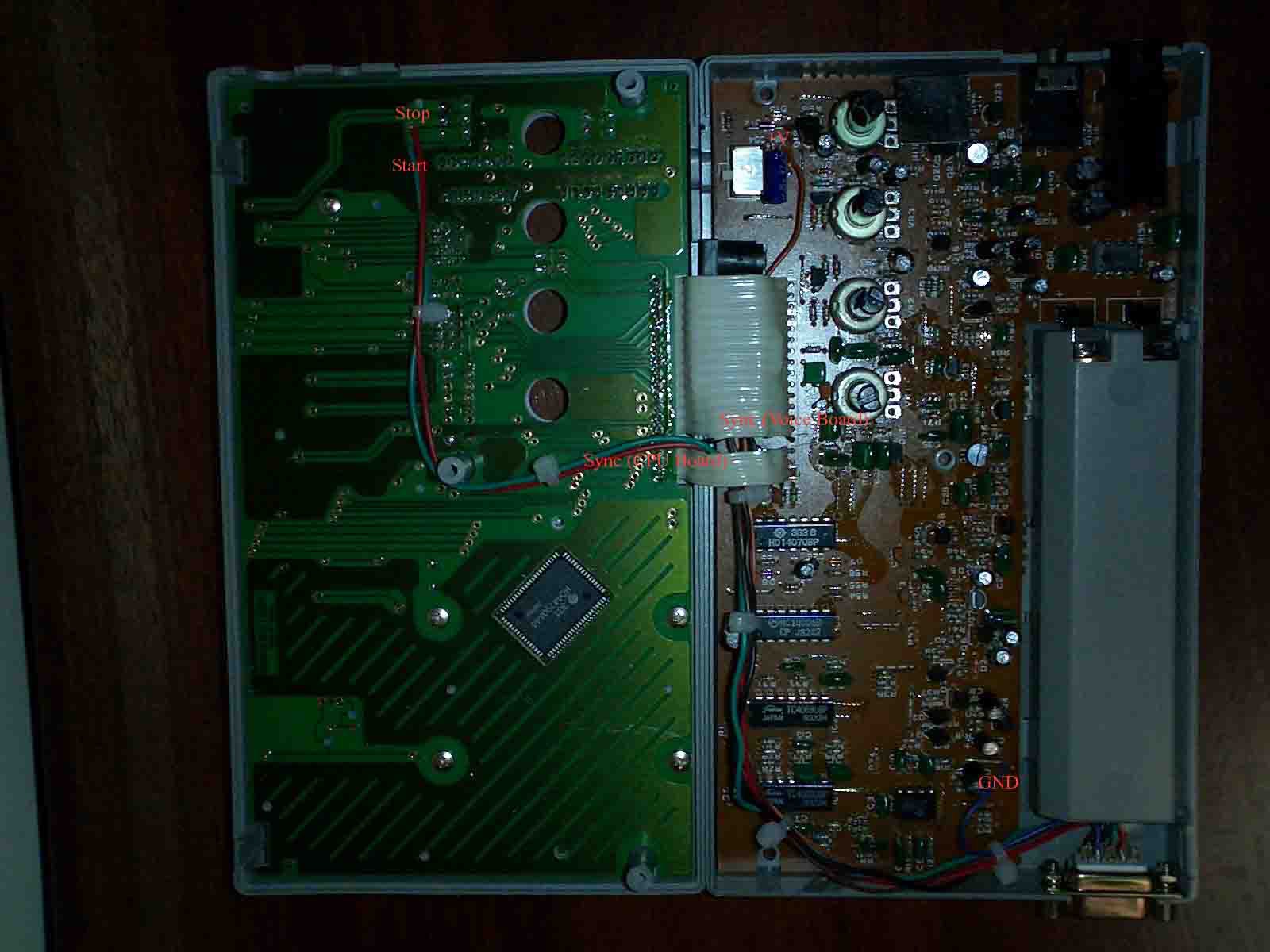
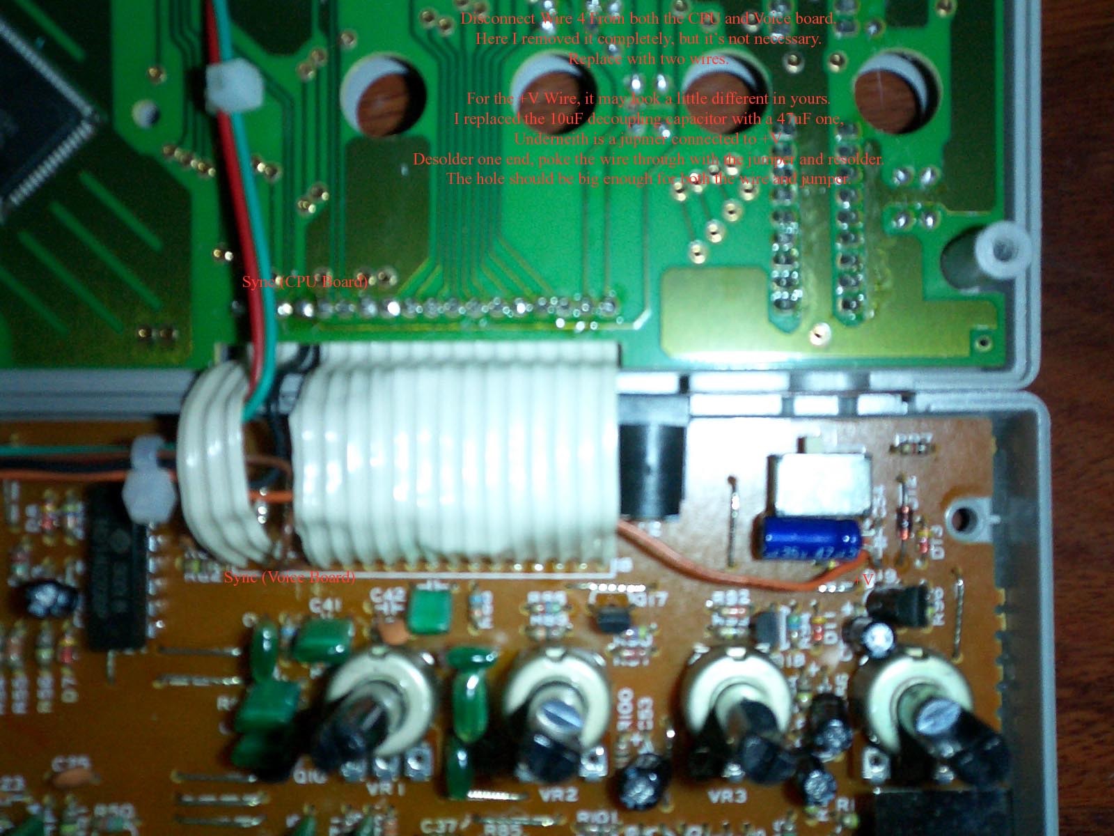
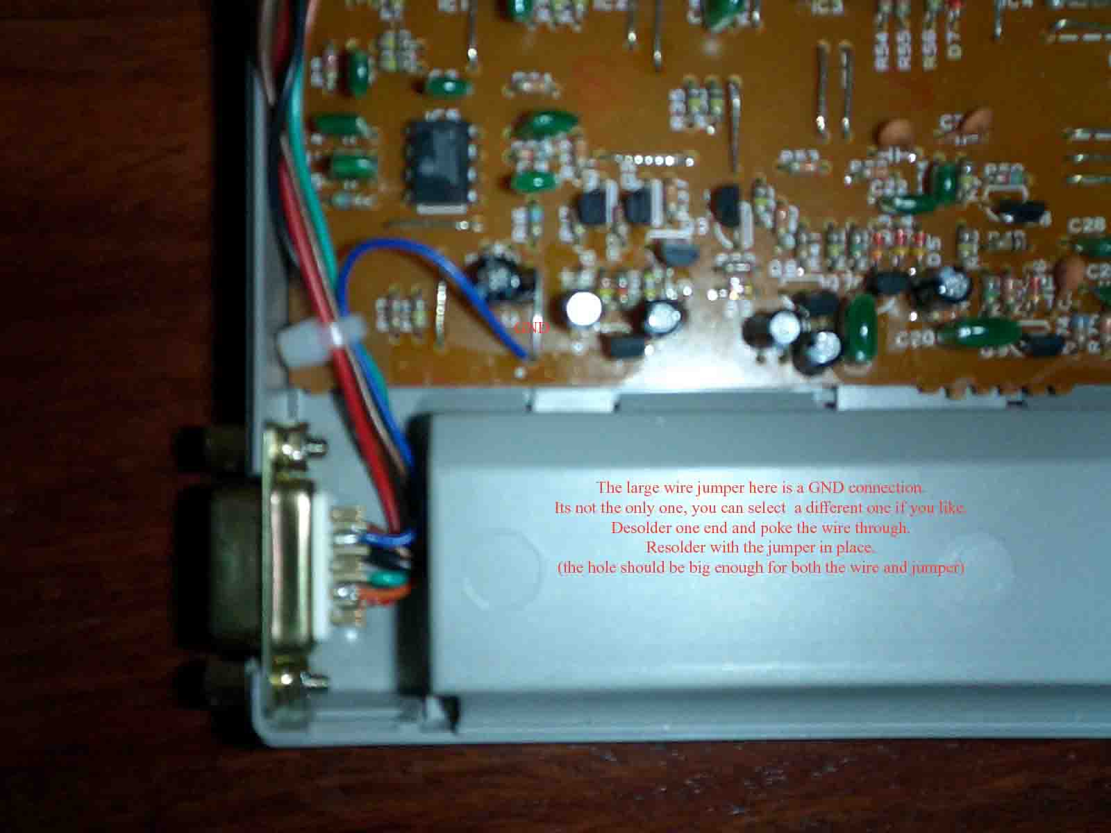
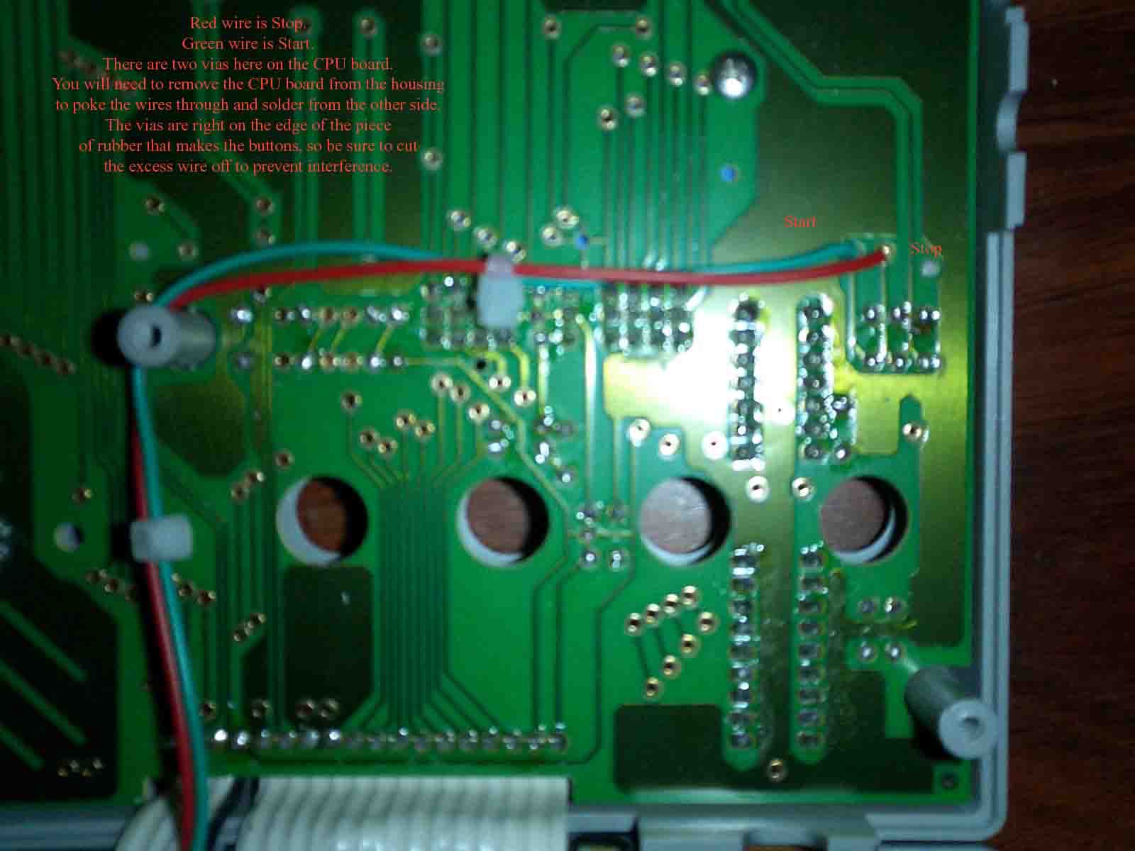
The circuit has 6 wires that need to be connected to the DR-110 internals. I powered the circuit from the internal power supply (2 wires). A start and stop wire need to be wired to the CPU board (2 wires). The final two wires are for the sync pulse. Wire 4 of the ribbon cable running from the voice board to theCPU board needs to be removed and replaced with two wires. One wire being the sync in (on the CPU board), the other beingthe sync out (voice board). The six wires run to a DB9 connector grafted into the side of the unit. You don't have to use a DB9 connector, that's just how I did it.
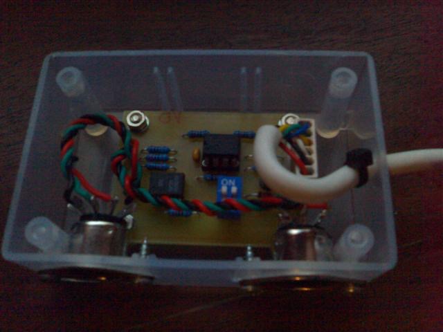
There was no room to put the new circuit and connectors inside the DR-110, I had to create an external circuit board.
The circuit is pretty strait forward. A 6N138 Opto-coupler is used for the MIDI input. R7 R8 and R9 limit the current on the output pins within the PIC spec. D1 is there to drop the supply voltage below 5.5V as required by the PIC specs. SW1 is a DPST switch (DPDT on the board) which acts to select the MIDI direction, and the DR-110 sync source.
Although updated, this version can still have problems with computer based sequencers. Computers have a tendency to spit out MIDI clock bytes in chunky dribs and drabs rather than a nice evenly timed stream.
FILES
Current Version
Source Code
(PIC12F675) - updated 10/4/2005
Schematic
works with both the current PIC12F675 and old PIC12C508 versions. .PDF format - updated 10/4/2005
Board layout
works with both the current PIC12F675 and old PIC12C508 versions. Designed to use panel mount MIDI jacks .PDF format - updated 10/4/2005
Component layout
works with both the current PIC12F675 and old PIC12C508 versions. Designed to use panel mount MIDI jacks .PDF format - updated 10/4/2005
Old Version
The original version of this project I implemented using a PIC12C508. Although it works, I had many problems syncing to my computers MIDI interface as the computer spits out sync bytes in chunky dribs and drabs, which this version could not handle well. It never had a problem syncing to a hardware sequencer or another drum machine.
Source Code
for PIC12C508 - updated 30/3/2004
Schematic
works only with the above old PIC12C508 source code .PDF format
Board layout
(PIC12C508 only) has PCB mount MIDI jacks. .PDF format
Component layout
.PDF format